- Home
- About us
- Products

- Services
- Contact us
- Downloads
- Company Profile
- PeeVee Catalogue
- Threaded Repair Catalogue Powercoil
- Black Oxide Surface Finish
- Fastener Markings - Bolts
- Fastener Markings - Nuts
- Nuts - Mechanical Requirements
- Chemical Component of Studs
- Common Abbreviations
- Mechanical Requirements Metric
- Conversion Chart
- Thread Terminology
- Terms & Conditions
- Downloads Video
- News
- Follow Us:


CALL US FOR ANY QUERY:
 011-49098640

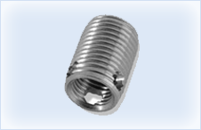
Products - Self Tapping Threaded Inserts - Bour Self Tapping Inserts
Buy Now
Hole Series - Key Features:
 Hole Series self threaded inserts are designed for use in tough-to-tap, high-strength materials as well as softer metals and plastics.
Highest pull-out resistance.
Suitable for harder materials.
Superior vibration resistance.
One-step installation.
Available certified to military standards.
Superior pull-out resistance in softer metals and plastics from the external v-form thread.
Circular cutting elements self-tap and lock into the base material. They are able to resist extreme vibration with no loss in performance.
High-quality internal threads are wear resistant, Unified and American Standard, class 2B, or ISO Metric standard, class 6H threads. Military versions conform to Unified and American Standard, class 3B.
This threaded insert is a solid metal bushing that is available in stainless steel, steel with zinc plating, or steel with cadmium plating in regular, medium or short length.
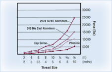
Performance Data*
| Internal Thread Size | Pull-Out Resistance (lb) | Tensile Strength (lb) of 160,000 PSI Heat-Treated Cap Screw | |||||
|---|---|---|---|---|---|---|---|
| Effective Shear Area | Phenolic | 380 Die Cast Aluminum | 2024 T4 Wrought Aluminum | ||||
| (in) | (metric) | (in)2 | (9,500 PSI Shear) | (26,000 PSI Shear) | (40,000 PSI Shear) | (in) | (metric) |
| 2 | 2 | 0.040 | 380 | 1040 | 1600 | - | 510 |
| 4 | 3 | 0.060 | 570 | 1560 | 2400 | 910 | 1250 |
| 6 | 3.5 | 0.090 | 860 | 2340 | 3600 | 1370 | 1680 |
| 8 | 4 | 0.130 | 1290 | 3380 | 5200 | 2120 | 2180 |
| 10 | 5 | 0.170 | 1620 | 4420 | 6800 | 2825 | 3520 |
| 1/4 | 6 | 0.270 | 2570 | 7020 | 10800 | 4800 | 4980 |
| 5/16 | 8 | 0.410 | 3900 | 10660 | 16400 | 7900 | 9080 |
| 3/8 | 10 | 0.610 | 5700 | 15860 | 24400 | 11700 | 14320 |
| 7/16 | - | 0.780 | 7410 | 20280 | 31200 | 16050 | - |
| 1/2 | 12 | 1.040 | 9880 | 27040 | 41600 | 21550 | 20910 |
| 9/16 | 14 | 1.230 | 11590 | 31720 | 48800 | 27200 | 28520 |
| 5/8 | 16 | 1.610 | 15300 | 41860 | 64400 | 34200 | 38940 |
| 3/4 | 18 | 2.360 | 22420 | 61360 | 94400 | 50500 | - |
Pull-Out Resistance or Tensile Strength
Specifications table key:
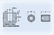
Refer to the 'Specifications' table below for the measurements that correspond to this diagram.