- Home
- About us
- Products

- Services
- Contact us
- Downloads
- Company Profile
- PeeVee Catalogue
- Threaded Repair Catalogue Powercoil
- Black Oxide Surface Finish
- Fastener Markings - Bolts
- Fastener Markings - Nuts
- Nuts - Mechanical Requirements
- Chemical Component of Studs
- Common Abbreviations
- Mechanical Requirements Metric
- Conversion Chart
- Thread Terminology
- Terms & Conditions
- Downloads Video
- News
- Follow Us:


CALL US FOR ANY QUERY:
 011-49098640

Products - Thread Repair Index - Reduce Diameter Inserts
Buy Now
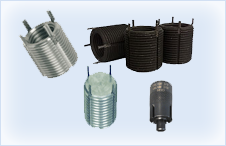
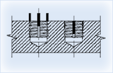 These solid - locking threaded inserts are ideal for thread reinforcement, especially when the mating stud or bolt will be removed frequently. They provide strong, permanent steel threads in any parent material -ferrous, non- ferrous, or non - metallic. Solid inserts are also well suited for quick repair of stripped, damaged, or worm threads. A solid version is also available to use as a handy plug to relocate holes drilled or tapped on the wrong location. Solid insert are available in carbon or stainless steel, bolt in inch and metric series. Thinwall, Heavy Duty, Extra heavy duty, and solid version styles are available separately. Installation tools are also available separately.
Locking keys are driven down into the parent material during installation. Providing a positive mechanical lock against rotation. Inserts with an ID thread 5/16 / 7mm and above have four locking keys. Smaller sizes have two.
Features :
 Install with standard drills and taps.
Important: Use tap and drill specified in table.
Tap-drill hole tolerance should be -.001/ .004 (-.001/ .005 above .500 dia).
Pull-out strength can be calculated approxi- thread 5/16 / 7mm and above have four locking keys. Smaller sizes have mately by following formula:
Approximate Shear Minimum ultimate
pull-out = engagement X shear strength of strength area of insert parent material
Installation Information
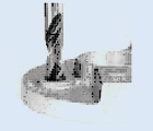
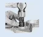
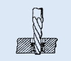
Drill out old threads using tap drill tap drill specified in table & Counter sink to diameter shown in table. (Correct tap drill is slightly latger than standard for the thread size)
Tap new threads using standard tap.
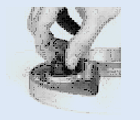
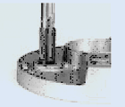
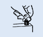
Screw in insert until body is slightly. (.010 to .030 inches) below the surface. Keys act as a depth stop.
Driver keys down with several light hammer taps on installation tool (or directly on keys)
Removal Information
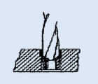
Drill out locking keys with specified drill diameter and depth (see table).
Deflect keys inward and break off.
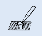
Remove insert with an E-Z out type tool.
Screw replacement into original Holes. Parent material is totally Undamaged